|
Can't find what you need? Request a disassembly manuals and we will try to locate it and add it to our database.
If you like this manual recomend it to your friends...
| | |
| |
| |
|
 |
STEP 1
It's crucial to remove the battery from the notebook before you start disassembly.
|
| |
|
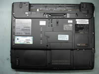 |
STEP 2
Remove the modem card cover, the hard drive cover, the memory module cover and the wireless card cover from the bottom of the notebook. Each cover is secured by one screw.
|
| |
|
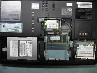 |
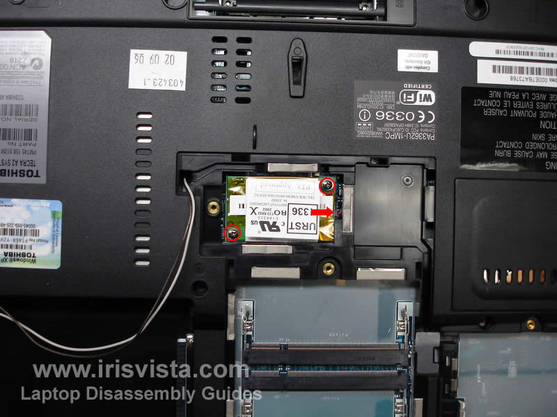
STEP 3
Removing the hard drive disk. Slide the hard drive to the left to disconnect it from the connector on the motherboard. After the hard drive is disconnected, lift it up and remove from the bay. If you are replacing the hard drive, you'll have to transfer the caddy to a new drive.
Removing the memory module. Spread the latches on both sides of the memory module until the module pops up. Pull the memory module from the slot.
Removing the wireless card. The Wi-Fi card has two antenna cables connected to it. Each cable has a small round connector (marked with a red circle). The whit cable is main and the black one is auxiliary. You can disconnect the antenna cables with your fingers. After antenna cables are disconnected from the wireless card, spread the latches on both sides of the card and pull the Wi-Fi card from the socket.
|
| |
|
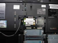 |
STEP 4
Pull the wireless card antenna cables from its route. The antenna cables have to be free before you remove the display assembly.
To remove the modem card, remove two screws first. After that carefully lift up the modem card to disconnect it from the motherboard and unplug the cable marked with a red arrow.
|
| |
|
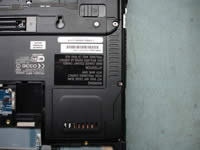 |
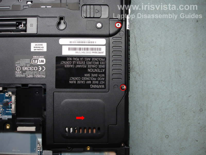
STEP 5
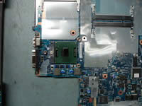
The CPU and the heatsink in this model could be easily accessed from the bottom of the notebook. To access them, you'll have to remove the cover first.
Remove two screws securing the cover and lift it up. |
| |
|
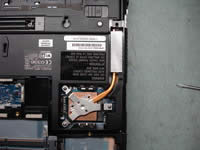 |
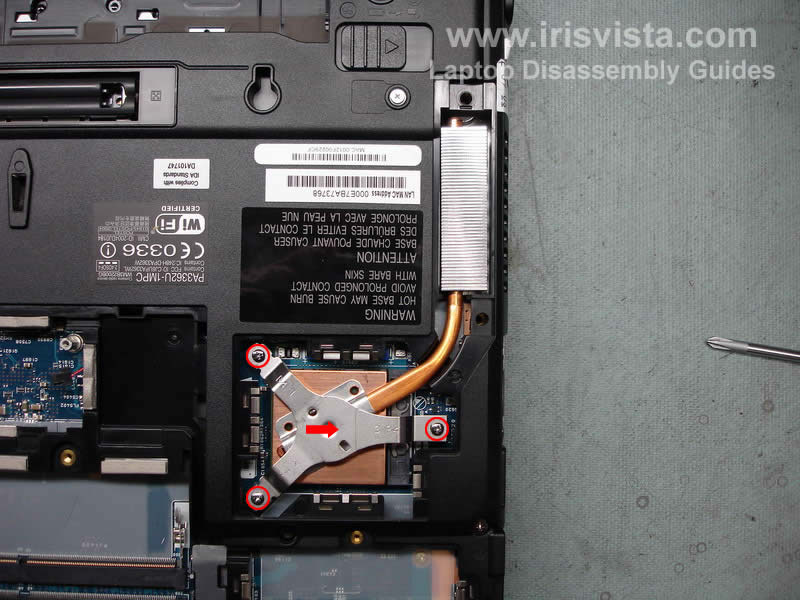
STEP 6
Remove three screws and remove a metal bracket securing the heatsink.
Lift up the heatsink from the CPU and remove old thermal grease from the heatsink and the CPU. You'll have to apply new layer of thermal grease before you assemble everything back. You can buy thermal grease in any local computer store.
If you need to replace the CPU, you can do it now. I'll remove it at the end of this disassembly guide.
|
 |
STEP 7
Remove all screws that secured the notebook base to the top cover.
|
|
| |
|
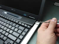 |
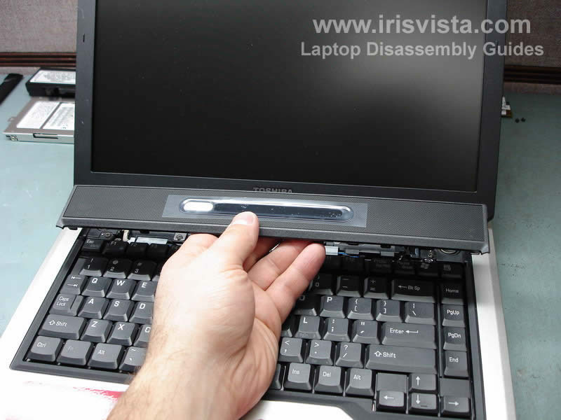
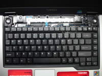
STEP 8
Turn the notebook over.
Now we are going to remove the keyboard bezel. You can use a flathead screwdriver. Insert it between the bezel and the base and carefully lift up. It's pretty easy to remove the keyboard bezel on this notebook.
|
| |
|
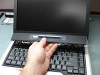 |
STEP 9
Remove the keyboard bezel.
|
| |
|
 |
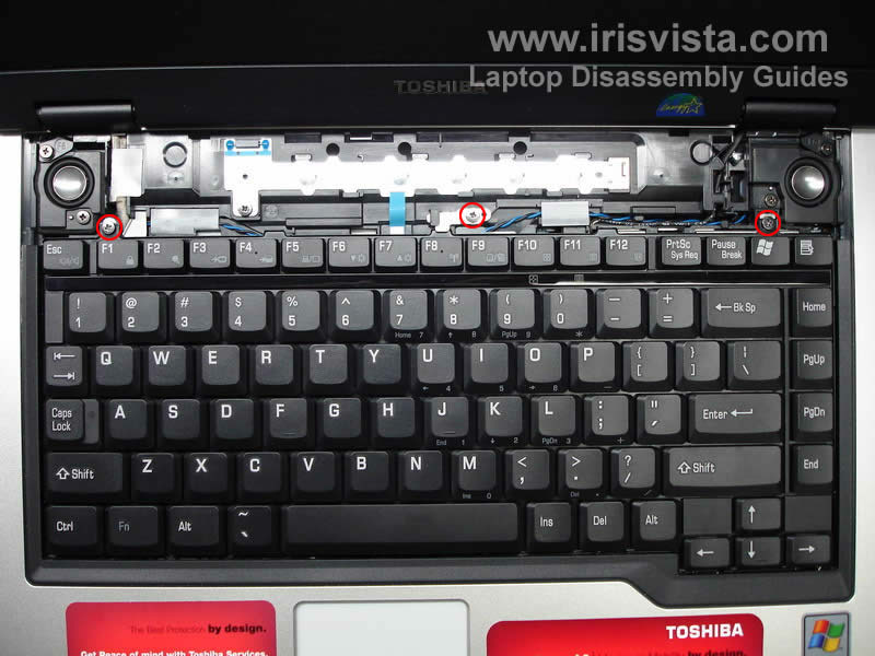
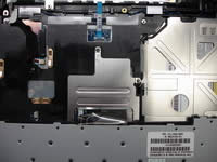
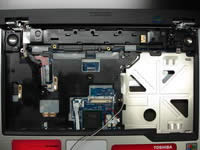
STEP 10
Remove three screws and a metal holder (in the middle) securing the keyboard.
Lift up the keyboard from the base and place it upside down on the palmrest.
Be careful, the keyboard cable is still attached to the motherboard.
|
| |
|
 |
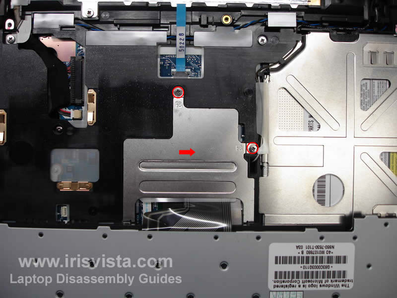
STEP 11
Remove two screws securing the metal plate over the keyboard connector and remove the plate.
The right screw also secures the DVD drive. So if you don't plan removing the keyboard and only replacing the DVD drive, remove only the right screw.
|
| |
|
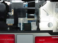 |
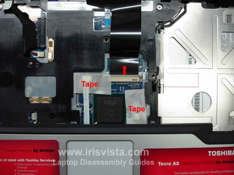
STEP 12
Connectors under the plate are covered with a tape. Remove the tape from the connectors.
Carefully open the keyboard cable connector on the motherboard by moving the lock (brown piece in my case) 2-3 millimeters in the direction shown by the red arrow. After the connector is open, pull the cable and remove the keyboard.
BE VERY CAREFUL WITH THE KEYBOARD CONNECTOR.
|
| |
|
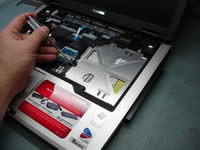 |
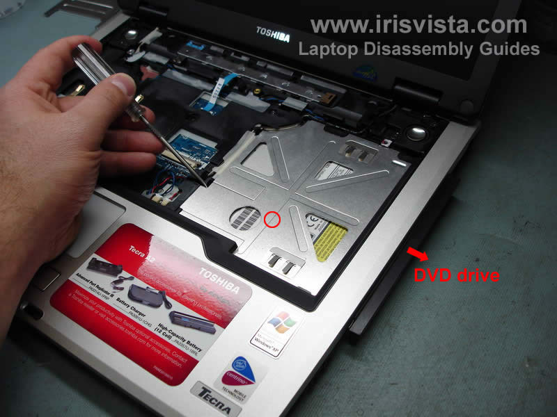
STEP 13
Push on the back of the DVD drive with a sharp object, as it shown on the photo and slide the DVD drive from the laptop.
Remove the DVD drive.
|
 |
STEP 14
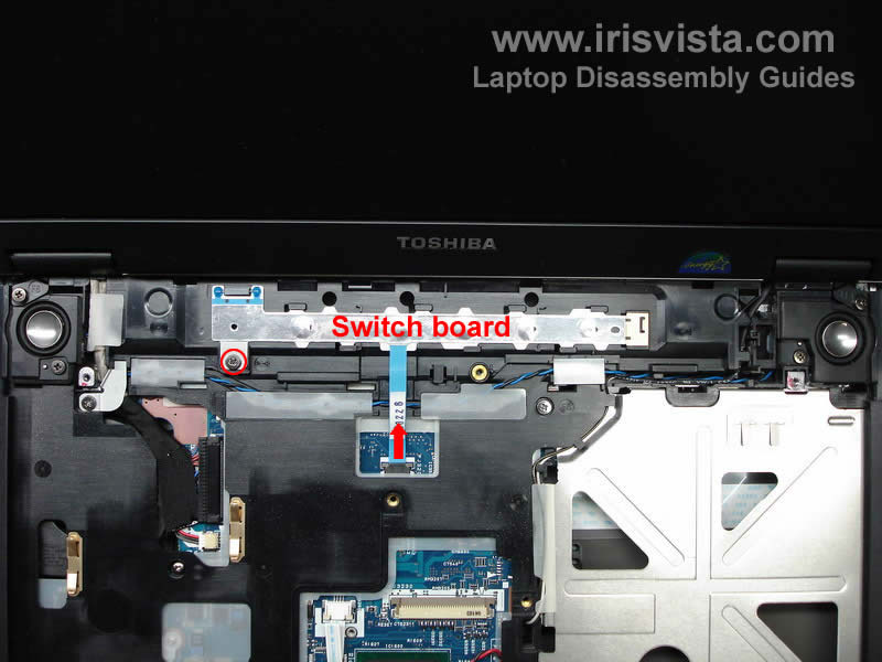
Open the switch board connector on the motherboard and pull out the cable.
Remove one screw securing the switch board to the top cover.
Slide the switch board to the left and lift it up.
|
|
| |
|
 |
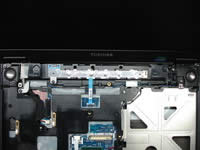
STEP 15
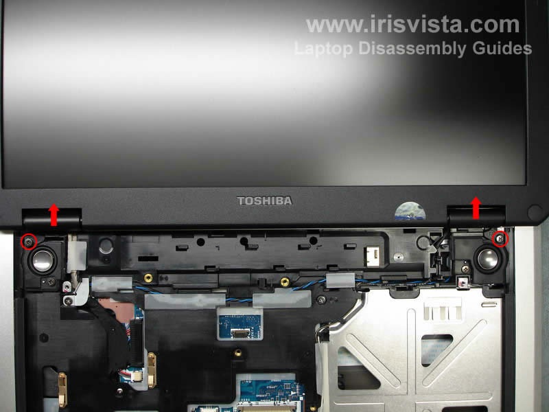
Remove two screws securing the left and right hinge covers.
Remove hinge covers, you can use a small flathead screwdriver to pry them up.
|
| |
|
 |
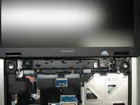
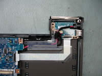
STEP 16
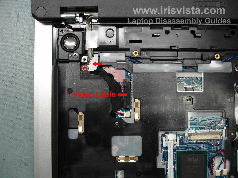
Remove one screw securing a metal bracket over the video cable. Remove the bracket.
Now we are going to unplug the display video cable from the motherboard. Be careful, do not pull for the wires. Unplug the video connector by the edges using your finger nails.
|
| |
|
 |
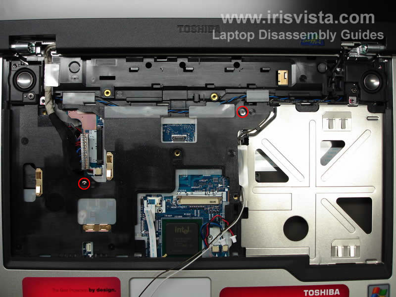
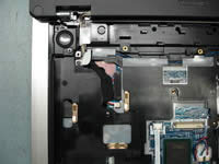
STEP 17
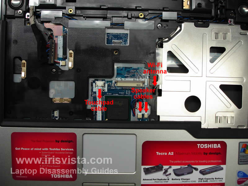
Open the touchpad cable connector on the motherboard and pull the cable out.
Unplug the left and right speaker cables.
Pull the wireless antenna cables through the opening in the top cover until the antenna connectors come out.
|
| |
|
 |
STEP 18
Remove two screws securing the top cover assembly.
|
| |
|
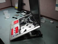 |
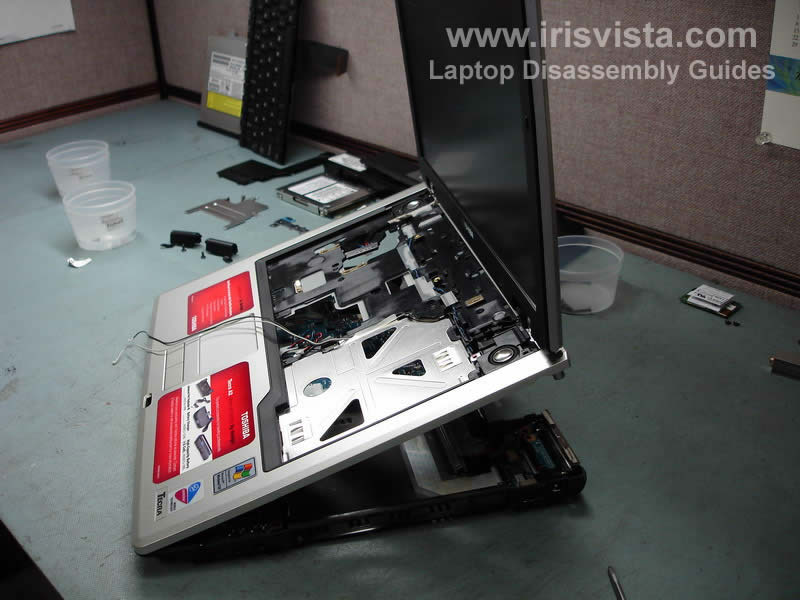
STEP 19
Start lifting up the top cover/display assembly as it shown on the photo. Move slowly.
Lift it up a little bit and take a look between the cover and the base, make sure that all cables are disconnected and nothing would be damaged when you split the parts.
Remove the top cover/display assembly from the notebook base.
|
| |
|
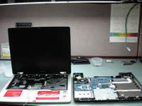 |
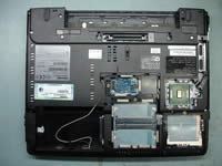
STEP 20
This photo shows the notebook in two halves. On the left side - the top cover/display assembly. On the right side - the notebook base with all boars inside.
|
 |
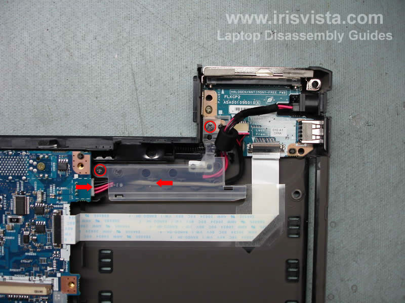
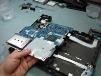
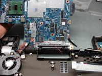
STEP 21
Remove two screws from a plastic cover that secures the power and USB board cables.
Lift up and remove the cover.
Unplug the power cable from the motherboard.
|
|
| |
|
 |
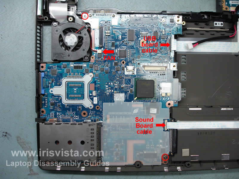
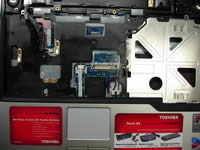
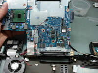
STEP 22
Open two connectors show with red arrows.
Pull the USB board flat cable and the sound board flat cable.
Remove two screws securing the motherboard to the notebook base.
|
| |
|
 |
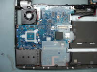
STEP 23
Start lifting up one side of the motherboard as it shown on the photo.
Do not remove the motherboard yet, there are still some cables connected to the other side.
|
| |
|
 |
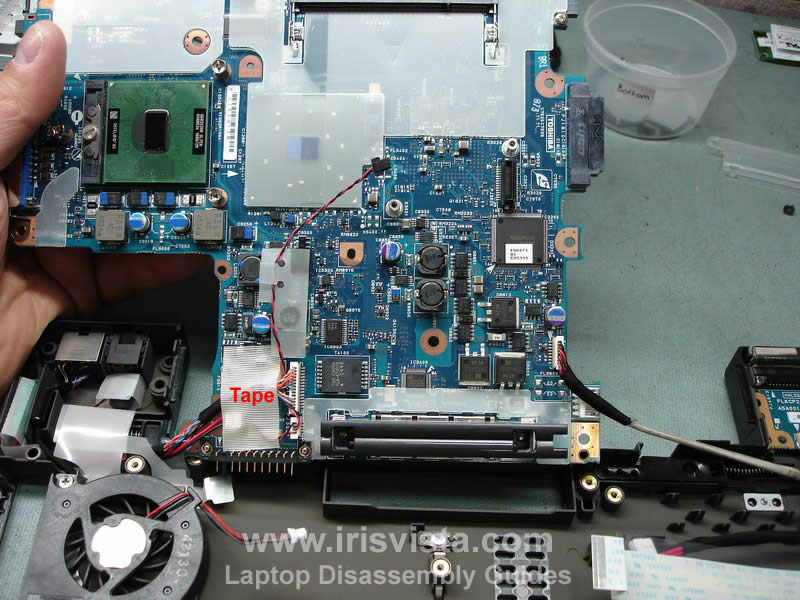
STEP 24
Turn the motherboard over. There would be a tape covering some connectors. Remove the tape.
|
| |
|
 |
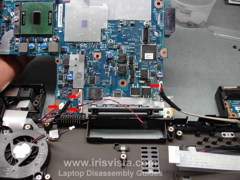
STEP 25
Unplug all cables that marked with a red arrow.
Even though all cables have differently sized connectors, I would recommend to draw a simple diagram (where each cable goes) so you are not confused when you assembled it back.
When all cables are unplugged, you can remove the motherboard and put it on your bench.
|
| |
|
 |
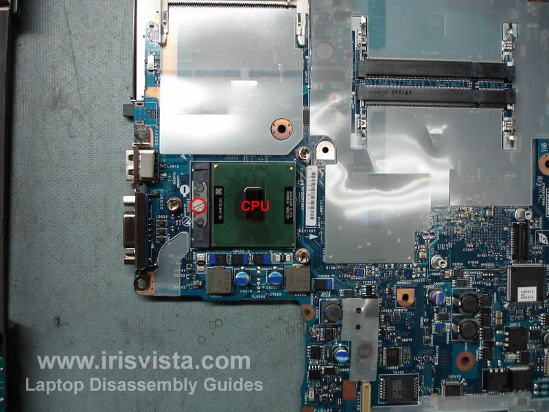
STEP 26
Finally, unlock the CPU socket by turning the screw into "open" position and lift up the CPU. Make sure that you lock the socket when you assemble it back. Also do not forget to apply a thin layer of thermal grease on the CPU surface before you install the heatsink.
If you forget to lock the CPU socket, the laptop will not boot up after you assemble it back.
If you forget to apply new thermal grease, the laptop will overheat and shut down.
|
|
| |
If you like this manual recomend it to your friends...
Search for Disassembly manuals
PinoutMaster team 2005 - 2024
Service manuals -
Car Audio Unlock-
Elemetnt Datasheets-
|